 |
|
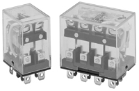
10A to 15A General purpose relay
 |
|
| 1. 15A switching capability, 1 Form C 2. Many variations and options available 3. Are suppression barrier standard (3P, 4P) 4. Conforms to various safety standard |
1. Ideal for many varied applications
![]() Dimensions (mm) and schematic
Dimensions (mm) and schematic
To convert into inches, multiply by 0.03937
![]() Contact data
Contact data
|
Contact
data
|
|||
|
Arrangement
|
1 Form C (SPDT) to 4 Form C (4PDT)
|
||
|
Contact material
|
Ag Alloy
|
||
|
Initial contact
resistance
|
50mΩ max.
|
||
|
Rated load,
resistive
|
1 Form C
|
2,3,4 Form C
|
|
|
15A 24VDC
15A 110VAC |
10A 24VDC
10A 110VAC |
||
|
Maximum carry
current
|
15A
|
10A
|
|
|
Maximum switching
capacity
|
with DC voltage:
with AC voltage: |
360W
1,650VA |
240W
1,100VA |
|
Maximum switching
voltage
|
125VDC
250VAC |
||
|
Minimum switching
rating1)
|
100mA 5VDC
|
||
1) Min. Switching Load
mentioned above are reference values. Therefore it is recommended to
perform the confirmation test with the actual load before production since reference
values may
vary according to switching frequencies, environmental conditions and expected
reliability levels.
![]() Coil data
Coil data
|
Coil
data
|
||
|
Nominal voltage
|
6VDC to 110VDC
6VAC to 240VAC |
|
|
Nominal power consumption2)
|
1P to 2P DC Coil:
3P to 4P DC Coil: 1P to 2P AC Coil: 3P AC Coil: 4P AC Coil: |
0.9W approx.
1.4W to 1.5W approx. 0.9VA to 1.2VA (60Hz) approx. 1.6VA to 1.9VA (60Hz) approx. 1.95VA to 2.5VA (60Hz) approx. |
|
Operate voltage3)
|
80% of nominal voltage
|
|
|
Release voltage4)
|
DC Coil:
AC Coil: |
10% of nominal voltage
30% of nominal voltage |
2), 3), 4) The values depend on coil voltage, see Part selection chart
![]() General data
General data
|
General
data
|
||
|
Operate time
|
25ms max. at nominal voltage
|
|
|
Release time
|
25ms max. at nominal voltage
|
|
|
Initial insulation
resistance
|
100 MΩ min. (500VDC)
|
|
|
Dielectric strength
|
Between open
contacts:
Between contacts & coil: |
1,000Vrms for 1 minute
1,500Vrms for 1 minute |
|
Expected life
|
Mechanical:
Electrical: |
More than 1,000,000 operations
More than 100,000 operations at rated load |
|
Vibration resistance
|
Functional:
Destructive: |
10∼55Hz dual amplitude: 1.0mm
10∼55Hz dual amplitude: 1.0mm |
|
Shock resistance
|
Functional:
Destructive: |
20G min.
100G min. |
|
Ambient temperature
|
-25℃ to +55℃ (with no icing)
|
|
|
Humidity
|
35% to 80% RH
|
|
|
Weight
|
1 and 2 Form C: 33g approx.
3 Form C: 53g approx. 4 Form C: 65g approx. |
|
Note: The above figures are initial values
![]() Part number description
Part number description
Part number description is provided for reference, part number can not be arbitrarily
composed.
Refer to the part numbers shown in the table below. Special designs to customer
specifications are
possible; please contact HR.
![]() Part selection
Part selection
Distributor stock item
□ Fill in the codes to the part number by selecting them from the part number
description
|
Part number
|
Nominal
voltage (VDC) |
Coil
resistance (Ω±10%) |
Nominal
current (mA) |
Must operate
voltage (VDC) |
Must release
voltage (VDC) |
Max
voltage (VDC) |
Nominal
power (W,VA) |
|
|
1 Form C, 2
Form C, DC Coil
|
||||||||
|
HR710-□□6VDC
|
6
|
40
|
150
|
4.8
|
0.6
|
6.6
|
0.9
approx. |
|
|
HR710-□□ 12VDC
|
12
|
160
|
75
|
9.6
|
1.2
|
13.2
|
||
|
HR710-□□ 24VDC
|
24
|
650
|
36.9
|
19.2
|
2.4
|
26.4
|
||
|
HR710-□□ 48VDC
|
48
|
2,600
|
18.5
|
38.4
|
4.8
|
52.8
|
||
|
HR710-□□ 100/110VDC
|
100/110
|
11,000
|
9.1/10
|
80/88
|
10/11
|
110/121
|
1.1 approx.
|
|
|
1
Form C, 2 Form C, AC Coil
|
||||||||
|
HR710-□□ 6VAC
|
6
|
12.2
|
214.1
|
183
|
4.8
|
1.8
|
6.6
|
1.0 to 1.2
(60Hz) approx. |
|
HR710-□□ 12VAC
|
12
|
46
|
106.5
|
91
|
9.6
|
3.6
|
13.2
|
|
|
HR710-□□ 24VAC
|
24
|
180
|
53.8
|
46
|
19.2
|
7.2
|
26.4
|
|
|
HR710-□□ 50VAC
|
48
|
788
|
25.7
|
22
|
40.0
|
15
|
55
|
|
|
HR710-□□100/110VAC
|
100/110
|
3,750
|
11.7/12.9
|
10/11
|
80/88
|
30/33
|
110/121
|
0.9 to 1.2
(60Hz) approx. |
|
HR710-□□ 110/120VAC
|
110/120
|
4,430
|
9.9/10.8
|
8.4/9.2
|
88/96
|
33/36
|
121/132
|
|
|
HR710-□□ 200/220VAC
|
200/220
|
12,950
|
6.2/6.8
|
5.3/5.8
|
160/176
|
60/66
|
220/242
|
|
|
HR710-□□ 220/240VAC
|
220/240
|
18,790
|
4.8/5.3
|
4.2/4.6
|
176/192
|
66/72
|
242/264
|
|
|
3
Form C, DC Coil
|
||||||||
|
HR710-□□ 3P 6VAC
|
6
|
25.7
|
234
|
4.8
|
0.6
|
6.6
|
1.4
approx. |
|
|
HR710-□□ 3P 12VAC
|
12
|
107
|
112
|
9.6
|
1.2
|
13.2
|
||
|
HR710-□□ 3P
24VAC |
24
|
410
|
58.6
|
19.2
|
2.4
|
26.4
|
||
|
HR710-□□ 3P
48VAC |
48
|
1,700
|
28.2
|
38.4
|
4.8
|
52.8
|
||
|
HR710-□□ 3P
100/110VDC |
100/110
|
8,500
|
12.7/13
|
80/88
|
10/11
|
110/121
|
||
|
3 Form C, AC
Coil
|
||||||||
|
HR710-□□ 3P
6VAC |
6
|
6.7
|
310
|
270
|
4.8
|
1.8
|
6.6
|
1.6 to 1.9
approx. (60Hz) |
|
HR710-□□ 3P
12VAC |
12
|
24
|
159 |
134
|
9.6
|
3.6
|
13.2
|
|
|
HR710-□□ 3P
24VAC |
24
|
100
|
80
|
67
|
19.2
|
7.2
|
26.4
|
|
|
HR710-□□ 3P
50VAC |
50
|
410
|
38
|
33
|
40
|
15
|
55
|
|
|
HR710-□□ 3P
100/110VAC |
100/110
|
2,300
|
14.4/16
|
12.4/13.7
|
80/88
|
30/33
|
110/121
|
|
|
HR710-□□ 3P
200/220VAC |
200/220
|
8,650
|
9.0/10.0
|
7.7/8.5
|
160/176
|
60/66
|
220/242
|
|
|
4
Form C, DC Coil
|
||||||||
|
HR710-□□ 4P
6VAC |
6
|
25
|
240
|
4.8
|
0.6
|
6.6
|
1.5
approx. |
|
|
HR710-□□ 4P
12VAC |
12
|
100
|
120
|
9.6
|
1.2
|
13.2
|
||
|
HR710-□□ 4P
24VAC |
24
|
350
|
69
|
19.2
|
2.4
|
26.4
|
||
|
HR710-□□ 4P
48VAC |
48
|
1,600
|
30
|
38.4
|
4.8
|
52.8
|
||
|
HR710-□□ 4P
100/110 VAC |
100/110
|
6,660
|
15/15.9
|
80/88
|
10/11
|
110/121
|
||
|
4 Form C, AC
Coil
|
||||||||
|
HR710-□□ 4P
6VAC |
6
|
5
|
386
|
330
|
4.8
|
1.8
|
6.6
|
1.95 to 2.5
approx. (60Hz) |
|
HR710-□□ 4P
12VAC |
12
|
20
|
199
|
170
|
9.6
|
3.6
|
13.2
|
|
|
HR710-□□ 4P
24VAC |
24
|
78
|
93.6
|
80
|
19.2
|
7.2
|
26.4
|
|
|
HR710-□□ 4P
50VAC |
50
|
350
|
46.8
|
40
|
40.0
|
15
|
55
|
|
|
HR710-□□ 4P
100/110VAC |
100/110
|
1,600
|
22.5/25.5
|
19/21.8
|
80/88
|
30/33
|
110/121
|
|
|
HR710-□□ 4P
200/220VAC |
200/220
|
6,700
|
11.5/13.1
|
9.8/11.2
|
160
|
60/66
|
220/242
|
|
Note: All values in the chart are measured at 23℃