 |
|
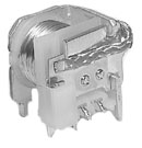
40A 1 Changeover power relay for automotive applications
| 1. Switching current 40A capability 2. Designed for high in-rush load 3. American and european foot print 4. Sealed type available |
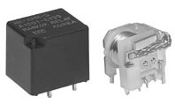 |
1. Cars, Buses, Coin machines and control systems
![]() Dimensions (mm)
Dimensions (mm)
To convert into inches, multiply by 0.03937
![]() PC Board Layout
PC Board Layout
Copper-side view
![]() Schematic
Schematic
Copper-side view
![]() Dimensions (mm)
Dimensions (mm)
To convert into inches, multiply by 0.03937
![]() PC Board Layout
PC Board Layout
Copper-side view
![]() Schematic
Schematic
Copper-side view
![]() Contact data
Contact data
|
Contact
data
|
||||
|
Arrangement
|
1 Form A (SPST) to 1 Form C (SPDT)
|
|||
|
Contact material
|
Ag Alloy
|
|||
|
Initial contact
resistance
|
100mΩ
|
|||
|
Rated load,
resistive
|
1 Form A
|
1 Form B
|
1 Form C
|
|
|
40A
|
30A
|
NO: 40A
NC: 30A |
||
|
Maximum switching
current
|
60A
|
|||
|
Maximum switching
capacity |
with DC voltage:
|
560W
|
420W
|
NO: 560W
NC: 420W |
|
Maximum switching
voltage1)
|
150VDC
|
|||
|
Minimum switching
rating2)
|
100mA 5VDC
|
|||
1) If switching voltage
is greater than 30VDC, special precautions must be taken. Please contact HR
2) Min. Switching Load mentioned above are reference
values. Therefore it is recommended to
perform the confirmation test with the actual load before production since reference
values may
vary according to switching frequencies, environmental conditions and expected
reliability levels.
![]() Coil data
Coil data
|
Coil
data
|
||
|
Nominal voltage
|
6V to 24V
|
|
|
Nominal power consumption2)
|
1.0W to 1.9W
|
|
|
Operate voltage3)
|
Standard coil:
High sensitive coil: |
70% of nominal voltage
75% of nominal voltage |
|
Release voltage4)
|
5% of nominal voltage
|
|
2), 3), 4) The values depend on coil voltage, see Part selection chart
![]() General data
General data
|
General
data
|
||
|
Operate time
|
5ms max. at nominal voltage
|
|
|
Release time
|
3ms max. at nominal voltage
|
|
|
Initial insulation
resistance
|
1,00 M min. (500VDC)
|
|
|
Dielectric strength
|
Between open
contacts:
Between contacts & coil: |
500VACms for 1 minute
500VACms for 1 minute |
|
Expected life
|
Mechanical:
Electrical: |
More than 5,000,000 operations
More than 100,000 operations at rated load |
|
Vibration resistance
|
Functional:
Destructive: |
10∼55Hz dual amplitude: 1.5mm
10∼55Hz dual amplitude: 1.5mm |
|
Shock resistance
|
Functional:
Destructive: |
10G min.
100G min. |
|
Ambient temperature
|
-40℃ to +85℃
|
|
|
Humidity
|
45% to 85% RH
|
|
|
Weight
|
open type:
sealed type: |
17g approx.
21g approx. |
Note: The above figures are initial values
![]() Part number description
Part number description
Part number description is provided for reference, part number
can not be arbitrarily composed.
Refer to the part numbers shown in the table below. Special designs to customer
specifications
are possible; please contact HR.
![]() Part selection
Part selection
|
Part number
|
Nominal
voltage (VDC) |
Coil
resistance (Ω±10%) |
Nominal
current (mA) |
Must operate
voltage (VDC) |
Must release
voltage (VDC) |
Max
voltage (VDC) |
Nominal
power (mW) |
|
Standard coil
|
|||||||
|
HR-AMR
□-□□DC06 |
6
|
19
|
316
|
4.2
|
0.3
|
7.8
|
1.9
|
|
HR-AMR
□-□□DC12 |
12
|
90
|
133.3
|
8.4
|
0.6
|
15.6
|
1.6
|
|
HR-AMR
□-□□DC24 |
24
|
360
|
66.3
|
16.8
|
1.2
|
31.2
|
1.6
|
|
Sensitive coil
|
|||||||
|
HR-AMR
□-□□DC24H |
12
|
140
|
85.7
|
9.0
|
0.6
|
15.6
|
1.00
|
|
HR-AMR
□-□□DC24H |
24
|
500
|
48.0
|
18.0
|
1.2
|
31.2
|
1.15
|
Note: All values in the chart are measured at 23℃